MICROSTAR + SYSTEM MANUAL • page 3 of 21
Simplex, Inc., 270 Riverside Parkway Suite G Austell, GA 30168 • 678-214-6575 • Fax 678-214-6670
Printed in the USA. • www.simplexdirect.com
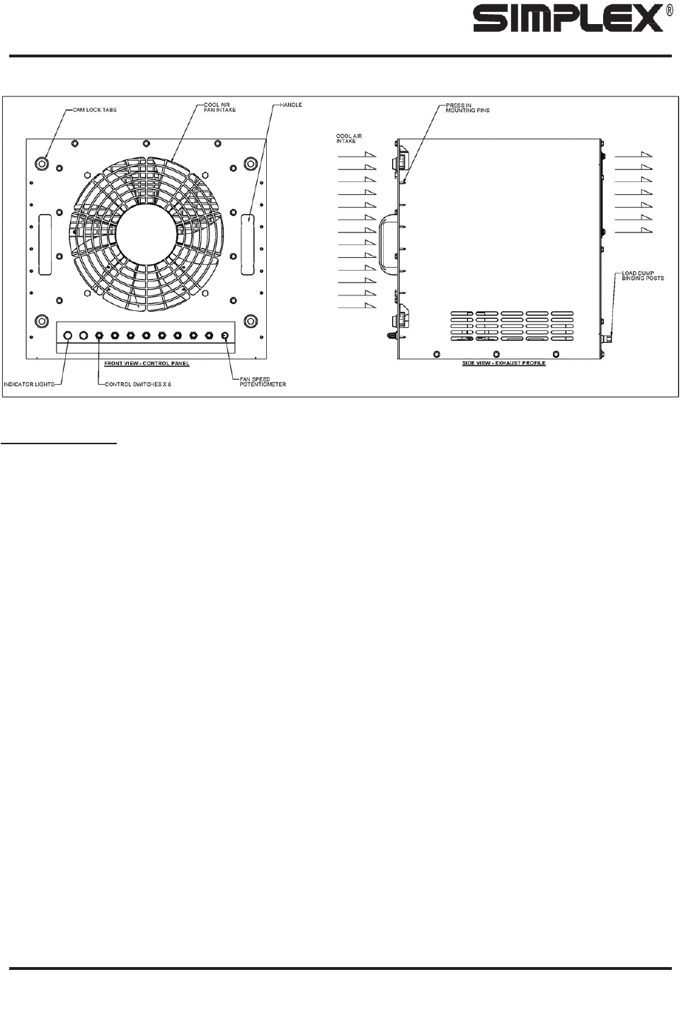
AIR FLOW AND VISUAL DIAGRAM
DESCRIPTION
Simplex Microstar + load bank units are precision test instruments specifically designed to apply discrete,
selectable heat loads to a cooling source. The Microstar + also provides a means for routine maintenance to
assure long term reliability of the product and readiness of the building cooling systems. The Microstar + fits
a 19-inch server rack of most all types, round/square/hole/threaded/unthreaded.
The cabinet on the Microstar + is rated Environmental Type 1.
The illustrations in this manual are examples only and may differ from your load bank.
Building cooling source testing is accomplished by applying resistive load steps to generate predetermined
amounts of heat (KW).
Load application is by magnetic contactor. Load steps 1-5 are protected by 15 amp class-CC fuses, and
load steps 6-7 are protected by 20 amp class-CC fuse.
Operating controls are provided locally via the control panel of switches located on the face of the unit. The
control system is composed of 24VDC components. Common serviceable components include control fuses
and load application fuses. Lamps on the face panel of the load bank indicate the operating status of the
Microstar +.
The local control panel contains the following components:
• Green “Cooling Active” Light
• Red “Over Temperature” Light
• On/Off Switch
• Fan Speed Potentiometer
• Load Steps 1-7
The “Cooling Active” lamp, green, illuminates when control power is available and the load may be applied.
Komentáře k této Příručce